Project Overview
For the EID-103 Principles of Design course, I collaborated with two fellow engineers to develop the "Homie Rektifier," a purely passive mechanical system designed to convert erratic, unidirectional rotary motion into a constant-velocity output without the use of electrical motors. Drawing inspiration from the geartrain mechanics of a cheap hand-pressed mechanical fan, we engineered a multi-stage system capable of driving an output shaft at nearly uniform speed.
Mechanical Design & Prototyping
The system was modeled entirely in Onshape and iteratively manufactured using Prusa 3D printers. To achieve mechanical rectification, we separated the transmission into distinct subsystems:
- Cam & Lever Actuator: Converts the erratic input of a fluctuating stepper motor into reciprocating motion using a spring-loaded lever.
- Sliding Gear Mechanism: A custom gear train with a sliding gear at the end that selectively engages under sufficient torque to deliver unidirectional pulses of power.
- Inertial Flywheel: Acts as a mechanical energy reservoir, storing rotational inertia to filter out input fluctuations and maintain a constant output velocity.
Performance Results
The table below compares the raw angular velocity of the fluctuating stepper motor against the rectified output of the system. Across multiple input voltages, the mechanism achieved nearly a 95% reduction in velocity variance, demonstrating a highly stable and consistent rotational output.
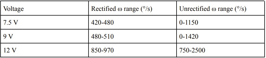
For comprehensive details regarding the iterative design process and full system specifications, please refer to the complete technical report below.
Mathematical Modeling & Control Theory
To validate the physical dynamics, fellow mechanical engineer Aleks Szetela and I developed a comprehensive theoretical model of the system using Laplace transforms. By mathematically modeling the electromechanical equations of the DC motor and all the subsystems, we derived the overall transfer function relating input voltage to output angular velocity. Using this model, we calculated the following key transient properties for the system:
- Natural Frequency: 32.6 rad/s
- Dominant Time Constant: 0.892 seconds
- Settling Time: 3.57 seconds
- Percent Overshoot: 0%
MATLAB Simulation
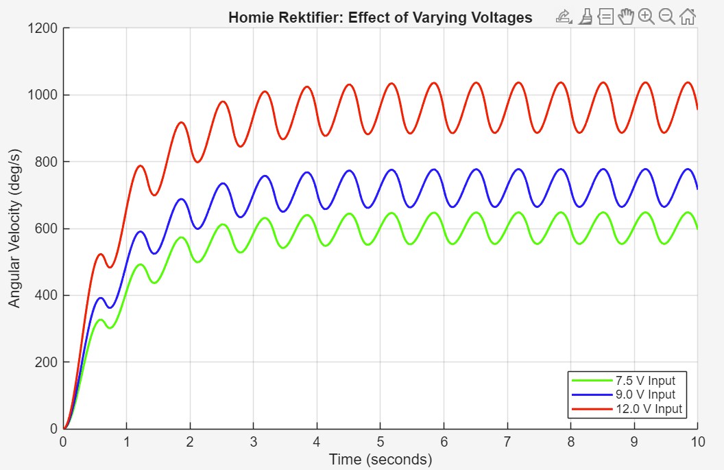
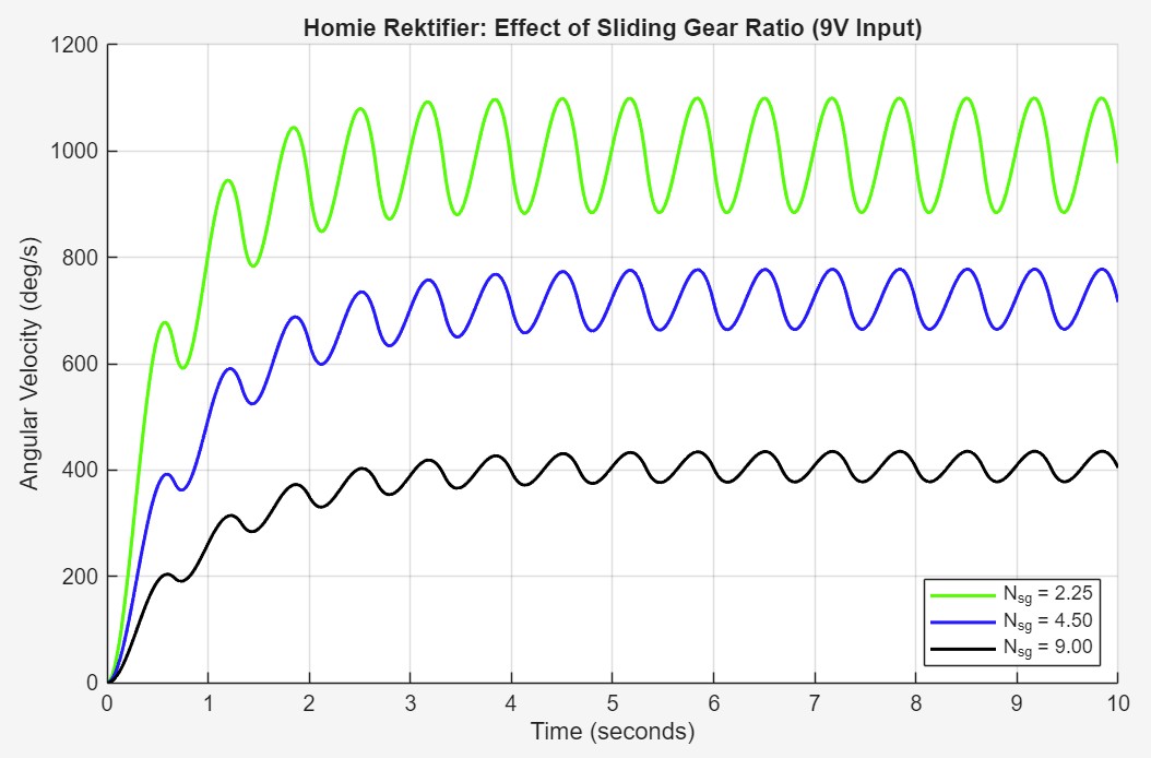
Using MATLAB, I simulated the system's step response to analyze the impact of varying motor voltages (7.5V, 9.0V, 12.0V) and sliding gear ratios (2.25, 4.50, 9.00). Generating these plots, shown below, allowed us to isolate the variables, clearly demonstrating the trade-off between higher output speeds and oscillation amplitudes. This data revealed 9.0V and a 4.50 gear ratio as the system's optimal operating voltage and gear ratio.
For a greater breakdown of the system dynamics, transfer functions, and MATLAB simulation, view the full technical presentation below.